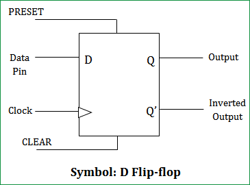
If it is 0, the flip-flop switches to the clear state.įigure 5. If it is 1, the flip-flop is switched to the set state (unless it was already set). The D input is sampled during the occurrence of a clock pulse. The D input goes directly into the S input and the complement of the D input goes to the R input. Introduction - D Flip-FlopThe D flip-flop shown in Figure 5 is a modification of the clocked SR flip-flop. When the pulse is removed, the state of the flip-flop is indeterminate, ie., either state may result, depending on whether the set or reset input of the flip-flop remains a 1 longer than the transition to 0 at the end of the pulse.įigure 4. With both S=1 and R=1, the occurrence of a clock pulse causes both outputs to momentarily go to 0. When the clock pulse goes to 1, information from the S and R inputs passes through to the basic flip-flop. The outputs of the two AND gates remain at 0 as long as the clock pulse (or CP) is 0, regardless of the S and R input values. Introduction - Clocked SR Flip-FlopThe clocked SR flip-flop shown in Figure 4 consists of a basic NOR flip-flop and two AND gates. This condition should be avoided in normal operation. When both inputs go to 0, both outputs go to 1. A 0 applied momentarily to the set input causes Q to go to 1 and Q' to go to 0, putting the flip-flop in the set state. Basic flip-flop circuit with NAND gates The NAND basic flip-flop circuit in Figure 3(a) operates with inputs normally at 1 unless the state of the flip-flop has to be changed. Basic flip-flop circuit with NOR gatesįigure 3. In normal operation this condition must be avoided by making sure that 1's are not applied to both inputs simultaneously.įigure 2. This condition violates the fact that both outputs are complements of each other. When a 1 is applied to both the set and reset inputs of the flip-flop in Figure 2, both Q and Q' outputs go to 0. The binary state of the flip-flop is taken to be the value of the normal output. The outputs Q and Q' are complements of each other and are referred to as the normal and complement outputs, respectively. When Q=0 and Q'=1, it is in the clear state (or 0-state). When Q=1 and Q'=0, it is in the set state (or 1-state). The flip-flop in Figure 2 has two useful states.

This type of flip-flop is referred to as an SR flip-flop or SR latch.

Each flip-flop has two outputs, Q and Q', and two inputs, set and reset. These flip-flops are shown in Figure 2 and Figure 3. Introduction - Basic Flip-Flop CircuitA flip-flop circuit can be constructed from two NAND gates or two NOR gates. Binary information can enter a flip-flop in a variety of ways and gives rise to different types of flip-flops. A flip-flop circuit has two outputs, one for the normal value and one for the complement value of the stored bit. The memory elements in a sequential circuit are called flip-flops. of Computer Science and Electrical Engineering The University of Queensland St.


 0 kommentar(er)
